
The 7 segment display is found in many displays such as microwaves or fancy toaster ovens and occasionally in non cooking devices. It is just 7 LEDs that have been combined into one case to make a convenient device for displaying numbers and some letters. The display is shown on the left. The pin out of the display is on the right.
This version is a common anode version. That means that the positive leg of each LED is connected to a common point which is pin 3 in this case. Each LED has a negative leg that is connected to one of the pins of the device. To make it work you need to connect pin 3 to 5 volts. Then to make each segment light up, connect the ground pin for that led to ground. A resistor is required to limit the current. Rather than using a resistor from each LED to ground, you can just use one resistor from Vcc to pin 3 to limit the current.
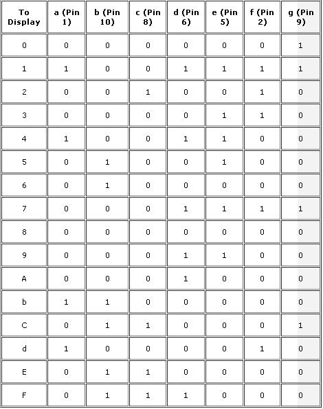
The following table shows how to form the numbers 0 to 9 and the letters A, b, C, d, E, and F. '0' means that pin is connected to ground. '1' means that pin is connected to Vcc.
Now, we want to run the display with the AT89C51 microcontroller. We will use Port 0 to run the display. Connect the AT89C51 to the 7 segment display as follows.
Program to display "0" on the seven segment display
Code (Text):
7 Segment display Interfacing with 8051 Microcontroller
Interfacing a 8051 microcontroller with a 7 segment Common Anode Display.
![[IMG]](http://www.8051projects.info/images/disp.gif)
![[IMG]](http://www.8051projects.info/images/display1.JPG)